Asked by Whian Bester on May 08, 2024

Verified
The Boolean equation for the logic represented in the ladder diagram can be expressed as: 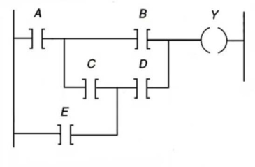
A) Y = (AB) + (ACD) + (DE)
B) Y = (AB) + (ACD) + (DE) + (BCE)
C) Y = (AB) + (AC) + (AD) + (ED)
D) Y= (AB) + (CD) + E
Boolean Equation
A mathematical expression that involves Boolean algebra and uses binary variables and logical operations, commonly used in computer science and digital electronics.
Ladder Diagram
a graphical representation used in programming PLCs that emulates the structure of electrical relay logic to control processes.
Logic Represented
Describes how logical states or operations are symbolized or implemented in programming or circuit design.
- Understand and utilize Boolean principles in ladder logic diagrams.
- Undertake the examination and construction of elementary parts and programming rungs in PLC systems.

Verified Answer
MM
manisha mallonMay 12, 2024
Final Answer :
B
Explanation :
The ladder diagram shows three inputs, A, B, and C, which are ANDed together. The output of this AND gate is then ORed with the output of another AND gate which has inputs C, D, and E. Finally, the output of this second AND gate is ORed with the input E. This can be written as Y = (AB) + (ACD) + (DE) + (BCE). Therefore, the correct choice is B.

Learning Objectives
- Understand and utilize Boolean principles in ladder logic diagrams.
- Undertake the examination and construction of elementary parts and programming rungs in PLC systems.